
Data Center Cooling Methods and the Problem Each One Fixed
Open Compute Project documents define cold plate cooling, indirect liquid cooling, and immersion as three separate methods. The field calls all of them liquid cooling, and calls the first one DLC, DTC, D2C, or direct-to-chip depending on who wrote the deck. HPE publishes the NVIDIA GB200 NVL72 at 132 kW per rack, 115 kW liquid cooled and 17 kW air cooled. That residual is the genealogy in one line: each method after air cooling shrank the air path without closing it.
Five names, one method, and a standards body that already settled it
DLC, DTC, D2C, direct-to-chip cooling and cold plate cooling name the same method. The OCP requirements document defines liquid cooling cold plates as closed loop cooling in which heat conducts through a plate attached to the component, and records that this is sometimes called direct liquid cooling. It separates out two things the term routinely swallows: indirect liquid cooling, where air carries the heat to the liquid as in a door heat exchanger, and immersion cooling, where components sit in direct contact with a dielectric liquid.
That same 2019 document lists the ASHRAE water classes as W1 through W5. The fifth edition of ASHRAE’s thermal guidelines renamed them after their ceilings and added a new class, W40.
Source: Open Compute Project, “ACS Liquid Cooling Cold Plate Requirements,” Revision 1.0 (October 9, 2019); ASHRAE TC9.9, “Emergence and Expansion of Liquid Cooling in Mainstream Data Centers” (2021)
This publication uses the OCP definitions for the rest of the series. A vendor sheet saying D2C and one saying DLC are not describing different hardware, and a reader comparing them is comparing nothing. W3 and W32 name the same envelope, while W40 has no old-name equivalent at all.
Table 1. Cooling terms and the definition each one maps toDefinitions as published
| Term as used in the field | What it means in this publication | Defining document |
|---|---|---|
| Liquid cooling | The family of methods, not a method. Says nothing about where the liquid meets the hardware | OCP, Rev 1.0 (2019) |
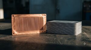
| Cold plate cooling, DLC, DTC, D2C, direct-to-chip | One method. Closed loop cooling, heat conducted through a plate attached to the component | OCP, Rev 1.0 (2019) |
| Indirect liquid cooling, rear door heat exchanger | Air is the transfer medium to the liquid. The server itself is still air cooled | OCP, Rev 1.0 (2019) |
| Immersion cooling | Components in direct contact with a dielectric liquid. Not cold plate cooling | OCP, Rev 1.0 (2019) |
| Hybrid cooling | Air cooling and direct liquid cooling in the same equipment. Room air conditioning still required | OCP, Rev 1.0 (2019) |
| Full liquid cooling | All heat rejected to liquid. Room neutral apart from unintentional losses | OCP, Rev 1.0 (2019) |
| W1 to W5 vs W17 to W+ | Classes renamed after their ceiling in the fifth edition, with a 2 °C lower limit on every class. W3 equals W32; W40 is new and has no old name | ASHRAE TC9.9 (2021) |
* Old W1 to W5 names persist in documents published before the 2021 fifth edition
* Immersion and door heat exchangers are both wet; neither is direct liquid cooling under these definitions
Source: Open Compute Project, “ACS Liquid Cooling Cold Plate Requirements,” Rev 1.0 (2019); ASHRAE TC9.9, “Emergence and Expansion of Liquid Cooling in Mainstream Data Centers” (2021)
Air cooling ran out of distribution, not out of air
Every extension of air cooling addressed the delivery path rather than the medium. ASHRAE TC9.9 cites a best-of-breed figure of 1900 cfm per floor tile against servers that require 100 cfm or more per U, which fills 19U of a rack and stops.
Fan power tells the same story from inside the chassis. The paper tracks it from as high as 20 percent of server power in the constant-speed era, down below 2 percent during the multicore period, and back up to 10 to 20 percent in dense servers.
Retaining air cooling while fan power climbs from 2 to 10 percent of server power cuts usable UPS capacity by 8 percent, since the fans sit behind the same UPS as the server.
Source: ASHRAE TC9.9, “Emergence and Expansion of Liquid Cooling in Mainstream Data Centers” (2021)
The committee puts the airflow of a 40 to 50 kW rack at up to 5000 cfm. Containment, in-row coolers and rear door heat exchangers each add a delivery or return path, and none of them changes what a cubic meter of air carries. The air cooling limit per rack describes a floor tile and a return path, not a property of air. That is why the fix turned out to be piping rather than better fans.
Cold plate cooling solved the socket and handed the rest back to air
Cold plate cooling moved the hottest components onto liquid and left everything else on the air path it inherited. The OCP classification is explicit about the split. Hybrid basic covers servers with CPU and GPU cold plates only, and the document states it is not uncommon for those plates to capture 70 to 75 percent of the IT equipment heat. Hybrid intermediate adds DIMM cold plates, and only the full liquid class brings the share close to 100 percent.
Shipping racks sit above that band. HPE lists the NVIDIA GB200 NVL72 at 115 kW liquid cooled out of 132 kW, which works out to 87 percent capture.
Source: Open Compute Project, “ACS Liquid Cooling Cold Plate Requirements,” Revision 1.0 (2019); HPE, “NVIDIA GB200 NVL72 by HPE” product page (accessed September 11, 2026)
The arithmetic behind the residual
Single-phase sensible heat transfer, the governing equation for any air path:
Q = ρ · V̇ · cp · ΔT, rearranged as V̇ = Q / (ρ · cp · ΔT)
Assumptions: ρ = 1.204 kg/m³ (dry air at 20 °C, 101.325 kPa); cp = 1.005 kJ/(kg·K); rack rise ΔT = 15 K, the value ASHRAE TC9.9 uses in its hot aisle worker safety example; 1 m³/s = 2,118.88 cfm.
- All 132 kW in air: 132,000 / (1.204 × 1005 × 15) = 7.27 m³/s = 15,410 cfm
- Hybrid basic at 70 to 75 percent capture, so 33.0 to 39.6 kW in air: 1.82 to 2.18 m³/s = 3,850 to 4,620 cfm
- The published 17 kW in air: 0.937 m³/s = 1,985 cfm
These are computed values, not measurements, and they scale inversely with the rack rise assumed. Against the best-of-breed floor tile, a fully air cooled rack at this power needs roughly eight tiles and the shipping configuration about one.
I read the gap between the OCP band and the HPE figure as a design generation rather than a disagreement, since the NVL72 puts cold plates on the NVLink switch trays as well. The ratio is not the useful number. A rack sold as liquid cooled still lands a full floor tile’s worth of air on the room.
Immersion closed the air path and moved the unsolved problem into logistics
Immersion is the first method here that removes the server air path instead of shrinking it. OCP defines it as direct contact between components and a dielectric liquid, and puts a fully immersed rack and a rack with a door heat exchanger in the same outcome class: room neutral, with only unintentional losses left for room air.
ASHRAE TC9.9 sets out the operating cost. Tank deployments often need a crane or a two-man lift to pull hardware for service, rack-based designs have to seal the fluid, and fluid interaction with hardware can affect warranty. Two-phase immersion then acquired a supply problem, when 3M announced in December 2022 that it would exit all PFAS manufacturing by the end of 2025, a category that covers the fluorinated fluids two-phase systems boil.
Source: ASHRAE TC9.9 (2021); 3M, “3M to Exit PFAS Manufacturing by the End of 2025” (December 20, 2022)
The unsolved problem in immersion was never thermal. Single-phase immersion works and is deployed. Two-phase immersion had its fluid supply regulated out from under it, a category of risk no thermal model produces.
Microfluidics attacks thermal resistance, which is a different variable
In-chip microfluidics is the first step in this genealogy that does not try to move more heat per unit of flow. It shortens the conduction path instead. Tuckerman and Pease demonstrated the principle in 1981 with a water-cooled microchannel heat sink etched into silicon, tested at 790 W/cm² with a maximum substrate temperature rise of 71 °C above the input water temperature.
Microsoft announced in September 2025 that it had tested an in-chip system with channels etched into the back of the die, reporting heat removal up to three times better than cold plates and a 65 percent reduction in the maximum temperature rise of silicon inside a GPU. Microsoft states both results are lab-scale and vary with workload, configuration and chip type, and describes production as work it is still pursuing with silicon partners.
Source: D. B. Tuckerman and R. F. W. Pease, “High-Performance Heat Sinking for VLSI,” IEEE Electron Device Letters, vol. 2, no. 5 (May 1981); Microsoft news release (September 2025)
Every method before this one raised the ρ · V̇ · cp · ΔT product. Microfluidics leaves that product alone and deletes the packaging layers between die and coolant. That is why its headline result is a temperature rise reduction rather than a capture percentage, and why it does not belong in the same column as the others.
Table 2. Heat left in air at each stage, for a 132 kW rackkW · cfm
| Stage in the genealogy | Where the heat goes | Heat left in air | Airflow for that heat |
|---|---|---|---|
| Air cooling only | Room air, through the floor and the return path | 132 kW | 15,410 cfm |
| Cold plate, hybrid basic (70 to 75% capture) | Liquid at CPU and GPU; air for the rest | 33.0 to 39.6 kW | 3,850 to 4,620 cfm |
| Cold plate, shipping rack (115 kW liquid, 17 kW air) | Liquid at CPU, GPU and switch trays | 17 kW | 1,985 cfm |
| Full liquid, or cold plate plus door heat exchanger | Liquid for all of it; room neutral | ~0 kW | ~0 cfm |
| Immersion, single-phase or two-phase | Dielectric liquid in direct contact; room neutral | ~0 kW | ~0 cfm |
| In-chip microfluidics | Liquid inside the die; research stage | n/a | n/a |
* Airflow computed from Q = ρ · V̇ · cp · ΔT at ΔT = 15 K, ρ = 1.204 kg/m³, cp = 1.005 kJ/(kg·K); scales inversely with rack rise
* Capture band and shipping rack figures come from different document types; not directly comparable
* Room neutral rows exclude unintentional thermal losses
Source: Open Compute Project, “ACS Liquid Cooling Cold Plate Requirements,” Rev 1.0 (2019); HPE, “NVIDIA GB200 NVL72 by HPE” product page (accessed 2026)
How strong the evidence is
The capture figures come from two kinds of document and are not equivalent evidence. The OCP band is a general statement about a design class with no test conditions attached. The HPE split is a published product figure whose measurement basis, workload and ambient conditions are not stated. The airflow values are computed at an assumed rack rise, so a site running a different rise gets different numbers. The microfluidics results are lab-scale and vendor-reported, without independent replication or published reliability data. Nothing here settles whether a particular rack can be cooled a particular way; flow rates, pressure limits, materials compatibility and leak response require engineering review against the actual equipment.
Source: Open Compute Project, Revision 1.0 (2019); HPE product page (accessed September 11, 2026); Microsoft news release (September 2025)
Reading a cooling proposal by capture share and W class
Read the capture percentage rather than the label. Ask which OCP class the equipment falls into: hybrid basic, hybrid intermediate, hybrid advanced, or full liquid.
Size the room air system for the residual, computed at the rack rise the site actually runs, rather than for zero.
Check which edition of the W classes a specification uses before comparing two of them. A sheet citing W4 and a sheet citing W45 agree. A sheet citing W3 and a sheet citing W40 do not.
Treat two-phase coolant as a supply chain item with regulatory exposure, and confirm a named supplier that is not winding the product down.
Separate serviceability cost from thermal performance when weighing immersion against cold plates. The two cases point in different directions, and the second is what technicians live with.
References
“ACS Liquid Cooling Cold Plate Requirements,” Revision 1.0 / Open Compute Project / October 9, 2019 / https://www.opencompute.org/documents/ocp-acs-liquid-cooling-cold-plate-requirements-pdf “Emergence and Expansion of Liquid Cooling in Mainstream Data Centers” / ASHRAE Technical Committee 9.9 / 2021 / https://www.ashrae.org/file%20library/technical%20resources/bookstore/emergence-and-expansion-of-liquid-cooling-in-mainstream-data-centers_wp.pdf “NVIDIA GB200 NVL72 by HPE” product page / Hewlett Packard Enterprise / undated / https://buy.hpe.com/us/en/compute/rack-scale-system/nvidia-nvl-system/nvidia-gb200-nvl72-by-hpe/p/1014890104 “High-Performance Heat Sinking for VLSI” / D. B. Tuckerman and R. F. W. Pease, IEEE Electron Device Letters, vol. 2, no. 5, pp. 126 to 129 / May 1981 / https://ui.adsabs.harvard.edu/abs/1981IEDL….2..126T/abstract “AI chips are getting hotter. A microfluidics breakthrough goes straight to the silicon to cool up to three times better.” / Microsoft / September 2025 / https://news.microsoft.com/source/features/innovation/microfluidics-liquid-cooling-ai-chips/ “3M to Exit PFAS Manufacturing by the End of 2025” / 3M / December 20, 2022 / https://news.3m.com/2022-12-20-3M-to-Exit-PFAS-Manufacturing-by-the-End-of-2025



댓글 0
첫 댓글을 남겨보세요.